39C3 RGB Catear Build Instructions

This guide aims to explain in simple terms how to assemble the c3cat catear build kit. If you did not get a hold of one of those kits, take a look at our BOM.
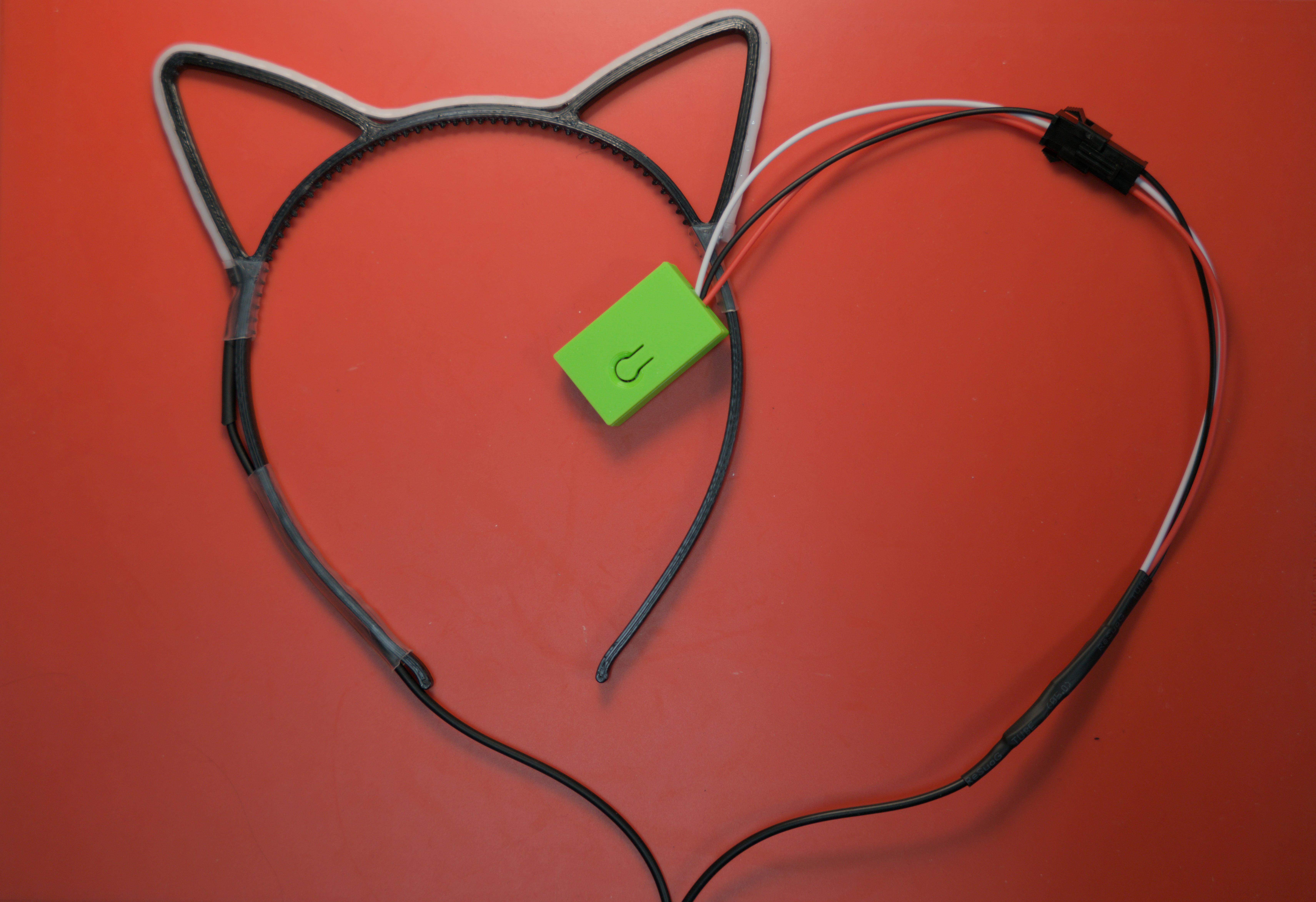
The general project assembly looks like this where each of the components must be connected via soldering points.
┌─────┐                          ╭───╮
│ ESP ├┄┄╼ ╾┄┄┄┄┄┄┄┄┄┄┄┄┄┄┄┄┄┄┄┄┄│   │
└─────┘
         ╱ ╲         ╱ ╲          ╱ ╲
     pluggable      long         catear
     connector      cable        & leds
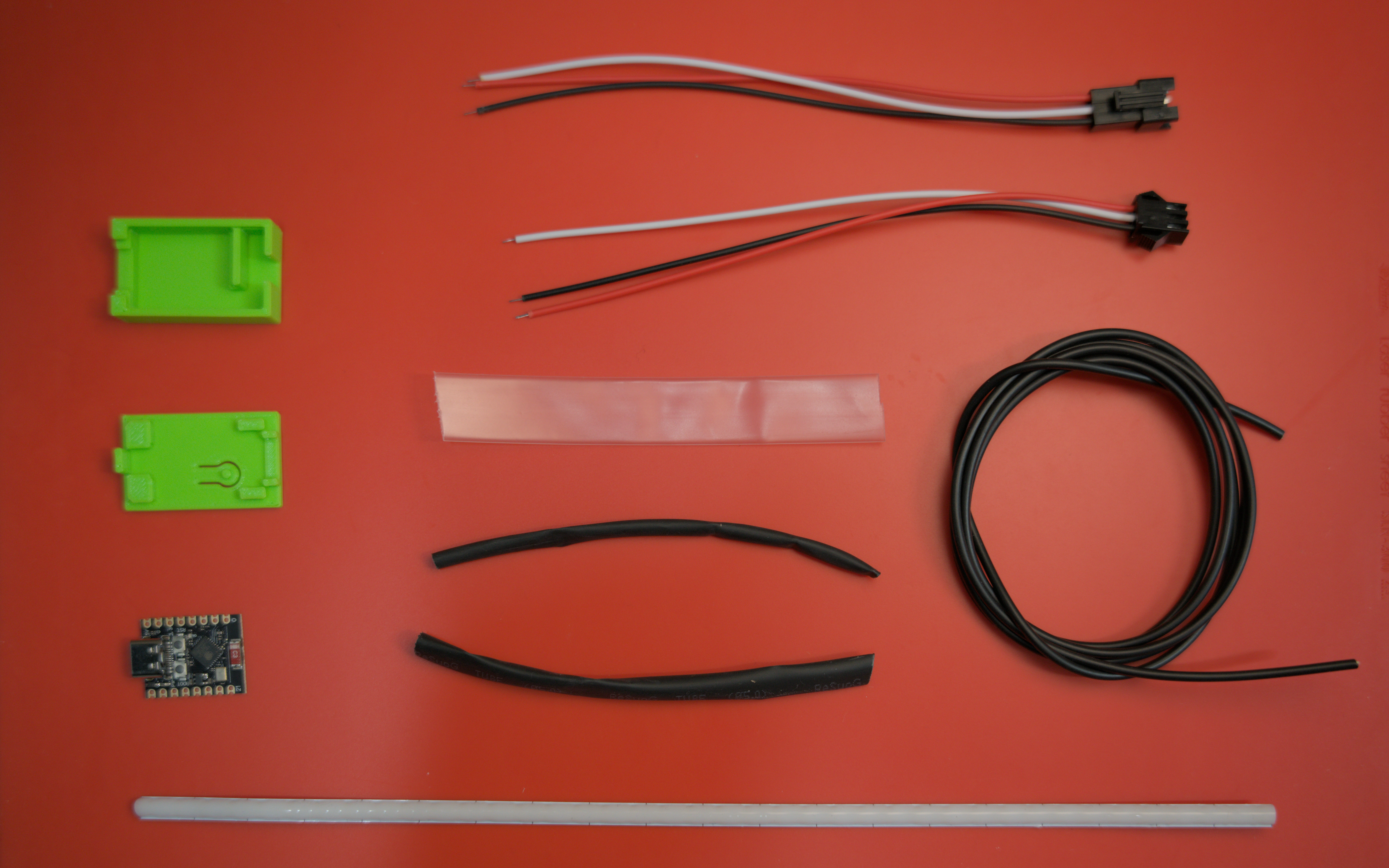
In addition to one of our kits, you will need
- soldering equipment
- a heatgun
- striping pliers
- catears
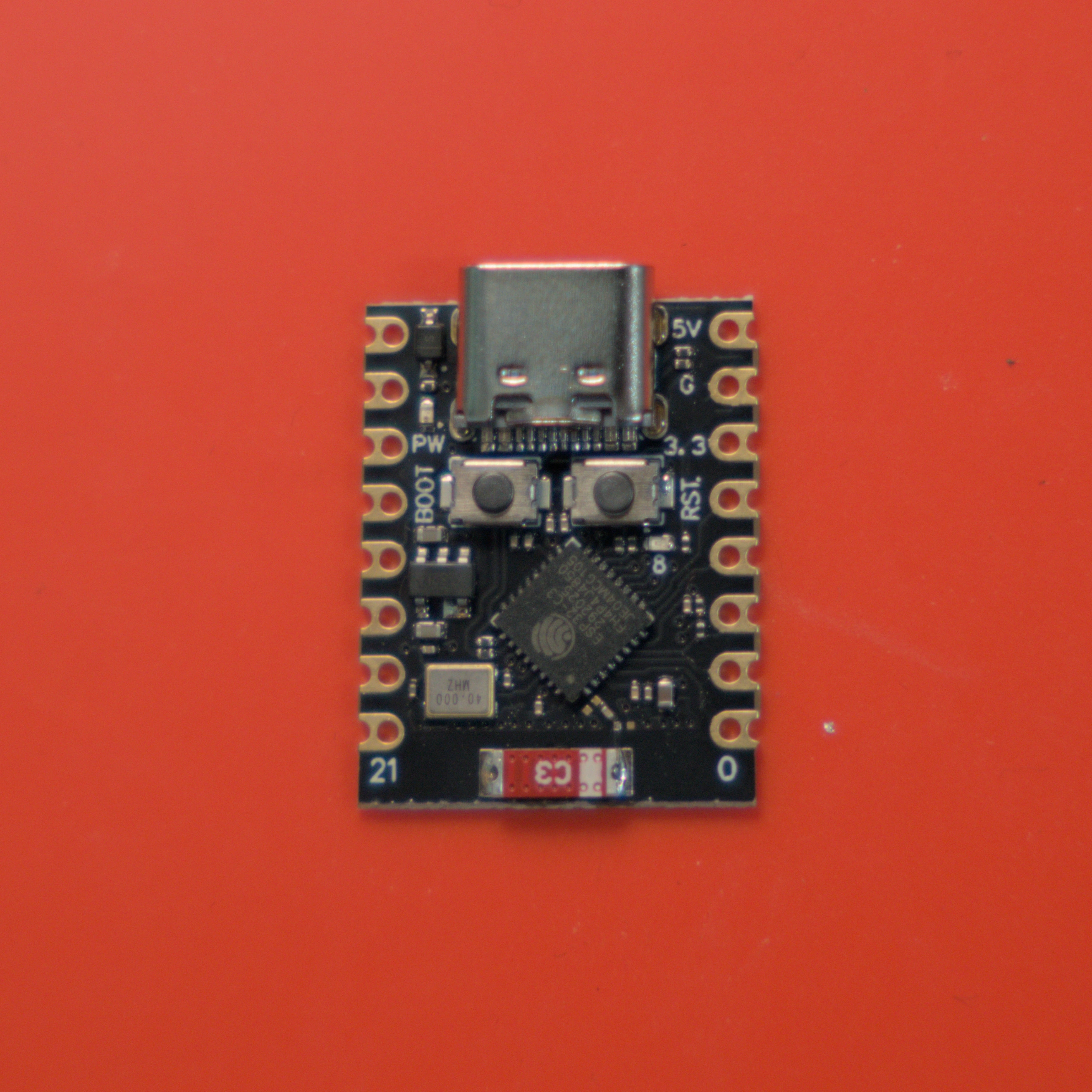
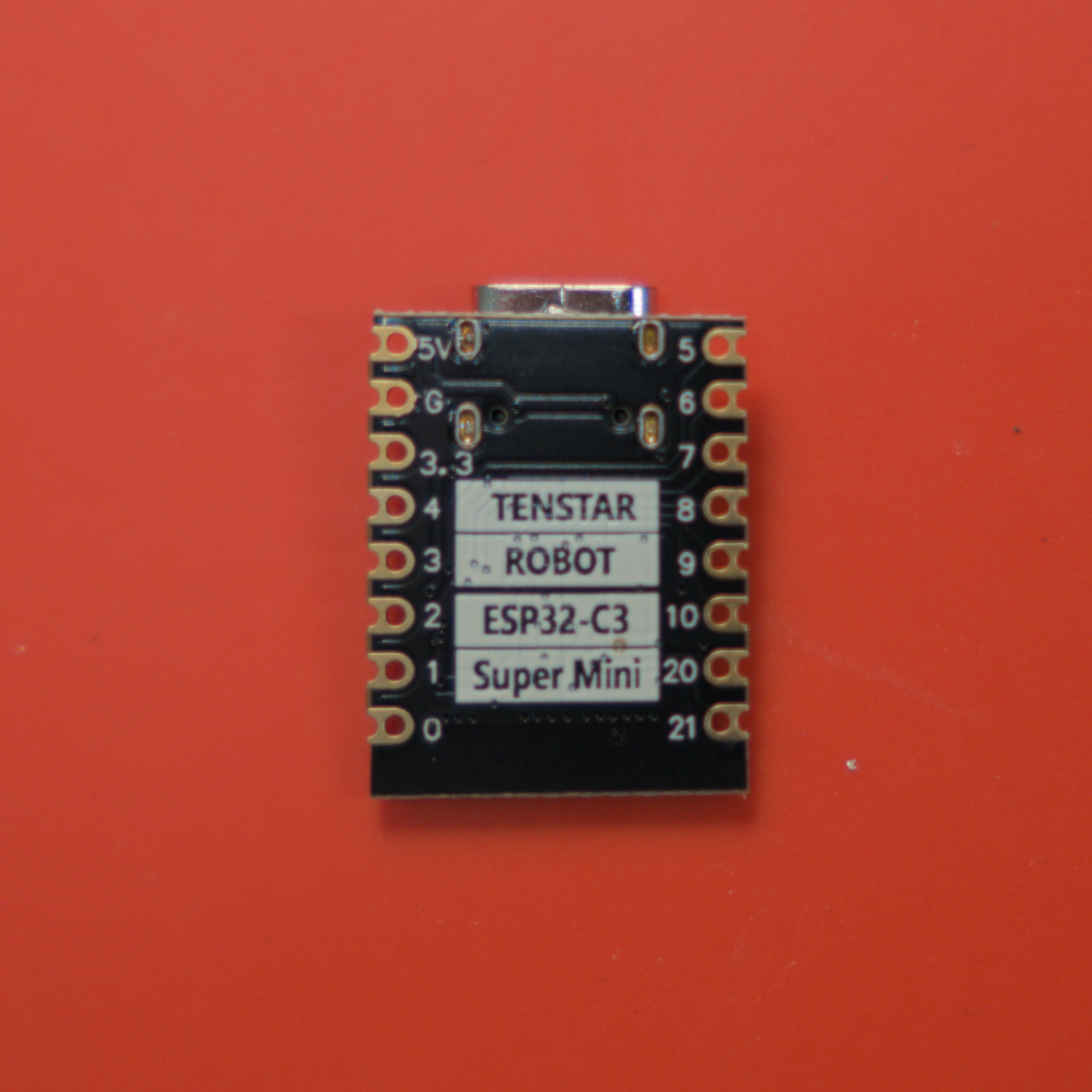
Flash the microcontroller §
We recommend to use WLED as a firmware on all our catears. It offers a wide range of features for display and animation and can be controlled comfortably from your smartphone.
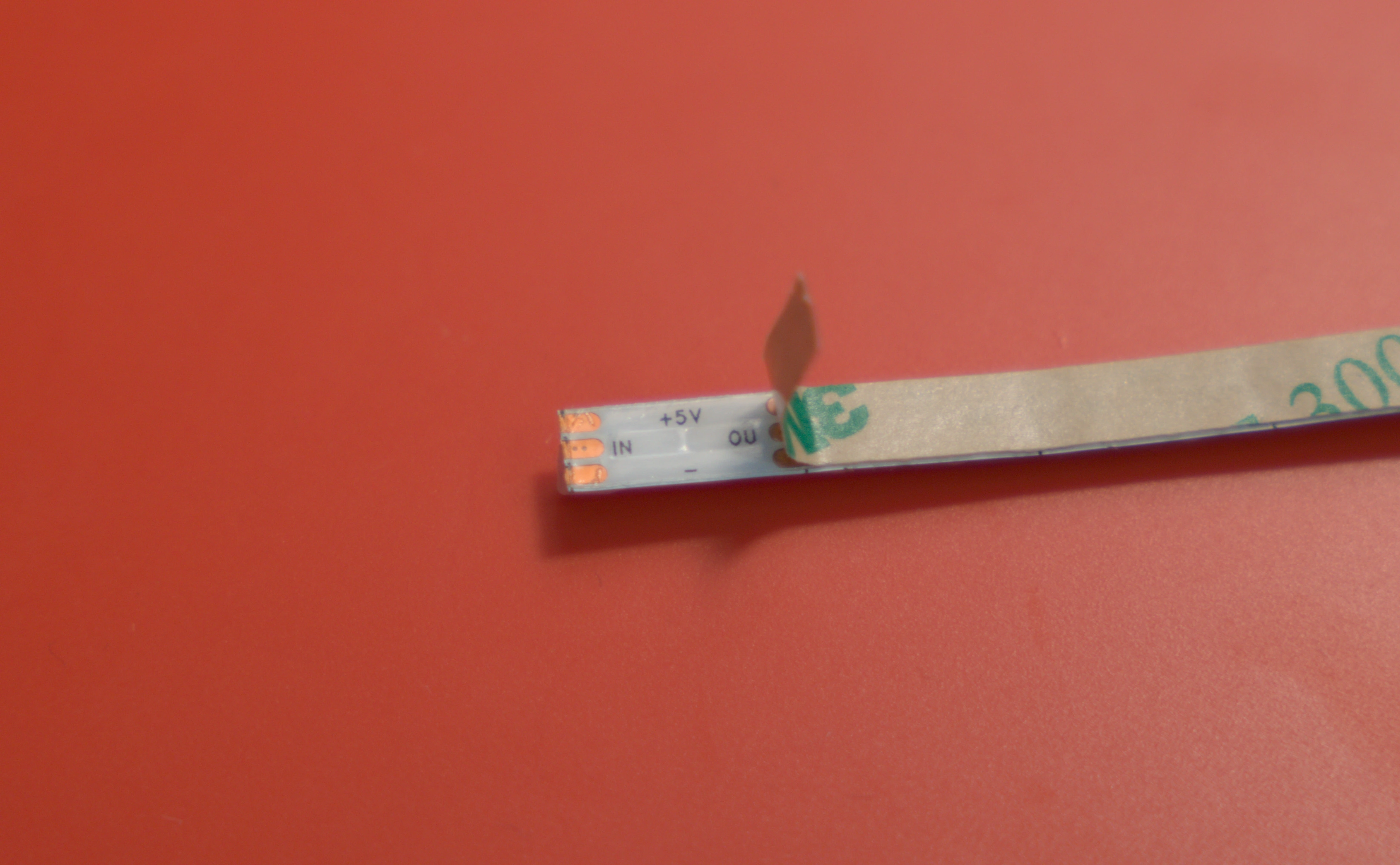
Solder cables to LED strip §
One of the most important steps is to electircally connect the microcontroller to the LED strip. We will start with the LED side.

Solder Cable to pluggable connector §
The other side of the long cable now needs to be connected to the pluggable connector.
Solder Pluggable Connector to Microcontroller §
Now you need to solder the other (female) part of the pluggable connector to your microcontroller.
Finalize the Assembly §
Congratulations! You now have a freely customizable pair of RGB catears :3
Don't feel pressured to wear cat ears – you're perfectly fine without them.
And remember: Trans rights are human rights.